Add CAD-Line
See also CAD-Line dialog
We add for you a CAD-Line from the start-Point to the end-Point of each Part you add to the model.
You can also edit a Part* to add one or more CAD-Lines to the Part in the Part-Editor.
Each Part you add to the model has a CAD-Line from its start-Point to the end-Point. Also, you can edit the Part to add to more CAD-Lines.
The Base-Part does not automatically have a CAD-Line. But, you can also edit the Base-Part to add to it one or more CAD-Lines.
* Part and Base-Part.
Use the CAD-Line dialog to:
•Import and display a SOLIDWORKS Part •Import and display an STL File •Import SolidWorks Mass-Properties •Edit the User Mass-Properties of the CAD-Line •Display a DXF-Drawing - before you can display the DXF-Drawing, you must File menu > Open DXF File •Change how to display the CAD-Solid |
Add CAD-Line
|
The CAD-Line is now in the graphics-area. See CAD-Line dialog |
|||||
To Add CAD-Line with a free start-Point and/or end-Point.
To Add CAD-Line with a merged start-Point and/or end-Point.
* Point, start-Point, end-Point, center-Point. |
||||||
Note : |
You can open the CAD-Line dialog from the: • Part-Editor, the Mechanism-Editor, and, if you import a CAD-Solid to the CAD-Line, the Model-Editor |
|||||
The CAD-Line in the graphics-area and Assembly-Tree
 CAD-Lines in an Added-Part |
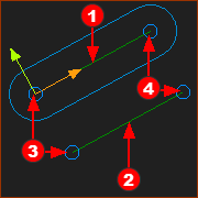
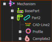
In the graphics-area: Mechanism-Editor : Add-Part - a CAD-Line Part-Editor : Add CAD-Line to add CAD-Lines Each CAD-Line has a Coordinate System, which is important to orientate a CAD file that you import onto the CAD-Line. The Coordinate-System is coincident with the Part's axes. You must remember or find the Coordinate-System of a CAD-Line that you add to the model. •+X–axis: from its start-Point •+Y–axis: at +90º from the +X–axis •+Z-axis: perpendicular to the Mechanism Plane (towards you in the default view (Front-View)) Note: A start-Point always has a lower element-number than the corresponding end-Point. Click the Points at each end of a CAD-Line to show their element-names in the Selection-Window. OR see View References. In the Assembly-Tree: •The CAD-Line is the only sketch-elements that show in the Assembly-Tree. •The Cad-Line is a child to a Part.
|
|---|---|
 Assembly-Tree: CAD-Line |