Element Properties dialog.
The Element Properties dialog lists an element's motion and force data at the Master Machine Angle.
Elements Properties are read-only. They may list:
oP : Position, or linear values
oV : Vector components (usually referred to the coordinates of the Mechanism-Plane)
o : Real Number
o|n| : Absolute Real Number
ox, y, Δx, Δy, Θ, ω, α, ΔΘ, Δω, Δα : Position and Angles, with motion-derivatives.
The Element Properties dialog can be open to read the properties at different Master-Machine Angles.
Note:
MD16-1-372 When you hover above any element in the graphics-area, the Element Properties show in the Extended-Hints box in the Feedback Area. MD17-1-134+ There is a check-box to show or hide the Element Properties dynamically in the Extended-Hints box - see Application-Settings > Accessibility tab > Menus & Toolbars > Show Element-Properties Dynamically. |
How to open the Element Properties dialog
|
In the graphics-area:
|
Element Properties dialog (read-only)
At the top of the dialog you can see the Element's Name, the name of the Element's Part, and Element's Mechanism.
The Element is a child to the Element's Part, and the Part is a child to the Element's Mechanism.
|
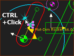
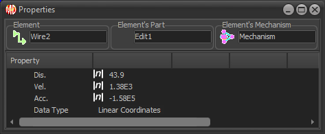
CTRL + Click a wire Wires connect and transfer, usually, Motion or Force data between Function-Blocks. A wire has a 3 Data-Channels, with three data-values. For example, the Data-Channels of a wire that controls the motion of a Motion-Part are Linear or Angular Displacement, Velocity, and Acceleration. |
|
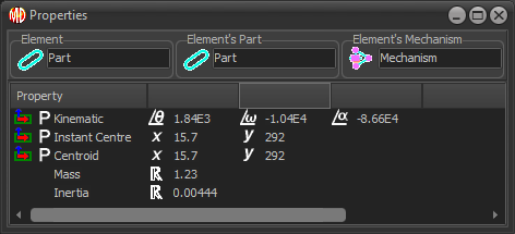
CTRL + Click a Part-Outline Properties: (P - Position) •Kinematic: Angle, Angular Velocity, and Angular Acceleration of Part relative to the Mechanism-Plane •Instant Center: The Part has an instant center of rotation: X and Y coordinates of the instant-center in the Mechanism-Plane •Centroid: X and Y coordinates of the Center of Mass in the Mechanism-Plane. •Mass: Value - Real Number •Inertia: Value - Real Number. |
|
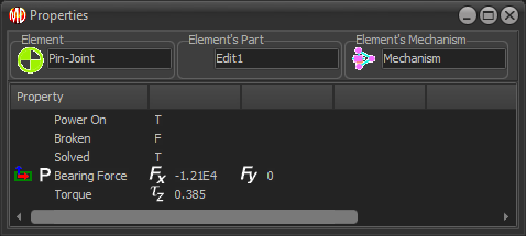
CTRL + Click a Pin-Joint Property: •Power On: True or False (T or F) - if the Pin-Joint is a Power Source - see Configure Power Source •Broken: True or False (T or F) - if the Pin-Joint does not solve (Broken) at this instant in the machine-cycle •Solved: True or False (T or F) - if the Pin-Joint is a child to a kinematic-chain that is kinematically-defined •Bearing Force oFx and Fy ; Vectors in Mechanism Coordinates •Torque oTz ; Vector normal to Mechanism Plane (if the Pin-Joint is the Power Source) |
|
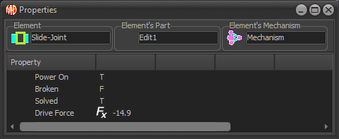
CTRL + Click a Slide-Joint Properties: •Power On: True or False (T or F) - if the Slide-Joint is the Power Source - see Configure Power Source •Broken: True or False (T or F) - if the Slide-Joint does not solve Broken) at this instant in the machine-cycle •Solved : True or False (T or F) - if the Slide-Joint is a child to a kinematic-chain that is kinematically-defined •Drive Force Fx ; Force along positive direction of Slide-Joint, if the Power Source is the Slide-Joint |
|
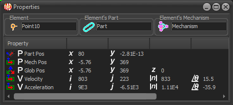
CTRL + Click a Point Properties: (P - Position ; V- Vectors) •P Part Pos: Position of the Point; Part Coordinates •P Mech Pos: Position of the Point; Mechanism Coordinates •P Glob Pos: Position of the Point; Global Coordinates (Z does not show!) •V Velocity, V Acceleration oi,j: the coordinates of the Velocity / Acceleration Vector, X and Y directions; Mechanism Coordinates o|n|: the magnitude of the Velocity / Acceleration Vector oΘ: the direction of the Velocity / Vector |
|
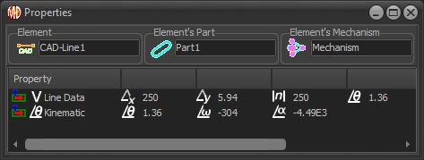
CTRL + Click a Line. Property: (V- Vectors) •Line Data: oΔx, Δy : the change in x and y from the Line's start-Point and end-Point o|n|: the length of the Line oΘ: the angle of the Line in the Mechanism-Plane •Kinematic: oΘ: the angle of the Line in the Mechanism-Plane oω : angular velocity of the Line oα : angular acceleration of the Line |
|
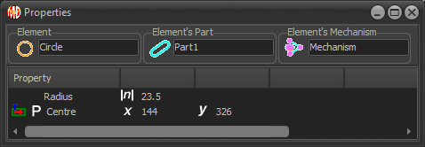
CTRL + Click a Circle. Property: (P - Position) •Radius: o|n|: the Radius of the Circle •center: ox and y : the position of the center of the Circle in Mechanism Plane |
|
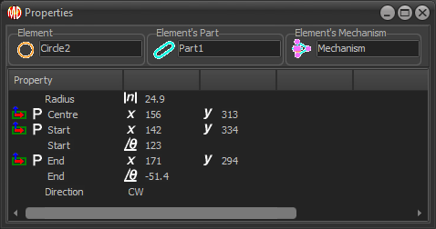
CTRL + Click an Arc. Property: (P - Position) •Radius: o|n|: the Radius of the Circle •center: ox and y : the position of the center of the Arc in the Mechanism-Plane •Start ox and y : the position of the start-Point of the Arc in the Mechanism-Plane oΘ : the angle of the start-Point from the center of the Arc •End ox and y, the position of the end-Point of the Arc in the Mechanism-Plane oΘ : the angle of the end-Point from the center of the Arc |
|
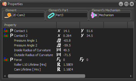
CTRL + Click a 2D-Cam. Property: (P - Position) Contact 1 and 2: ox and y: the coordinates of the contact between the Inner and Outer Cam-Profiles and the Follower-Profile. Pressure Angle 1 and 2: oΘ : the Pressure Angle of the Follower-Roller with the Inner and Outer Cam-Profiles Curvature 1 and 2: o|n| : the Radius of Curvature of the Inner and Outer Cam-Profiles Force oFx and Fy : the Contact Force of the Cam on the Roller, given in the X and Y directions, with Mechanism Coordinates If you have selected a Follower-Roller and Steel Type for a 2D-Cam with the 2D-Cam dialog: Roller L10 Lifetime [Hrs] - Lifetime in Hours of the Follower-Roller, Lubrication Conditions, and Factor-of-Safety that you select in the 2D-Cam dialog. Cam Lifetime [Hrs] - Lifetime in hours of the Cam-Profile (Outer or Inner), with the Steel Type, Heat-Treatment, Quality, Hardness, and Factor-of-Safety that you enter in the 2D-Cam dialog. |