Why edit a Part?
In all cases, use the Part-Editor to edit a Part.
These are a few of the many reasons to edit a Part :
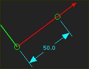
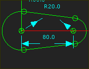
 Edit the Length of a Part
|
To edit the length of the Part, you must edit the dimension that controls the length of the CAD-Line. See also: Edit the Length of a Part |
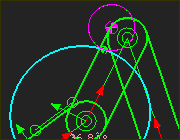
Add Points and Lines to locate Pin-Joints, Slide-Joints, and/or Ball-Joints
|
You can add new Lines, CAD-Lines, and Points to locate joints in a Part. Base-Part: You MUST add a minimum of one sketch-element to the Base-Part for a Pin-Joint or Slide-Joint between the Base-Part and a Part that you add to the model. We recommend you add a Line to the Base-Part as the first sketch-element. |
Add Points for Trace Points
|
You can add a Point to a moving Part and then select the Point to add a Trace-Point to view the trace of that Point on the Mechanism-Plane during a machine-cycle. See Mechanism-Editor: Add Trace-Point |
Add Sketch-Loops / Sketch-Paths
|
You must sketch a sketch-loop before you can add a Profile / Extrusion. Use the Part-Editor to add the sketch-elements for the sketch-loop.
|
Follower-Profiles
|
Each Cam needs a Follower-Profile. Add a sketch-loop for the Follower-Profile - typically a Circle. You must also sketch the shape of the Cam-Blank when you add a 3D-Cam. |
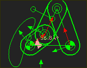
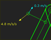
Plot exact Kinematic Data
|
For any Point* that you add to a Part, you can: •Show the instantaneous kinematic vectors (Velocity and Acceleration) of the Point with the Point Properties dialog •Plot motion-values of Position, Velocity and Acceleration throughout the machine-cycle with the Point-Data FB or Measurement FB that you connect to a Graph FB * Point, start-Point, end-Point, center-Point, and Motion-Point. |
Add a CAD-Line
You can add any number of CAD-Lines to any Part. You can use the CAD-Line to import DXF-Drawings, SolidWorks documents, or STL file-types. CAD-Lines can be coincident with each other, or at different positions in the Part. There is also a CAD-Line between the start-Point and end-Point of every Part that you add to the model. |
Constraint Based Editing Tools for Mechanism Synthesis
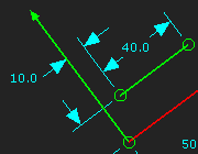
You can add Constraints to and between sketch-elements for any number of reasons. |
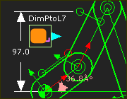
To add sketch-elements for a Measurement FB dimension
|
Occasionally, you must add sketch-elements to Parts to measure the distance with a Measurement FB. See Add Measurement FB. The output from a Point-Data FB is position, velocity and acceleration of a Point. You can use the output of a Measurement FB or Point-Data FB as the independent variable (X-axis) for a different FB. |
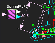
Add a Point or Line for a Spring FB
|
Add a Point* to anchor a Spring FB. * Point, start-Point, end-Point, center-Point, and Motion-Point.
|
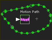
Add a sketch-loop for a Motion-Path and Motion-Point.
|
A Motion-Path FB adds a Motion-Point to a sketch-path in a Part. Edit the Motion-Path FB to add more Motion-Points. |