Cam-Data FB > Cam-Analysis
To analyze a 2D-Cam:
Action |
Step in this topic: |
|---|---|
1.Add a Cam-Data FB |
see STEP 1 |
2.Link the Cam-Data FB to a 2D-Cam |
see STEP 2 |
3.Connect wires to a Graph FB |
see STEP 3 |
STEP 1: Add Cam-Data FB
To add a Cam-Data FB to the graphics-area:
The Cam-Data FB is now in the graphics-area and Assembly-Tree. Note: Typically, add a CAM-Data FB for each 2D-Cam in your model. TOP-TIP - if there is more than one 2D-Cam in your model
|
|||||
STEP 2: Link the Cam-Data FB to a 2D-Cam
To link the Cam-Data FB to a 2D-Cam, you must first open the Cam-Data dialog. To open the Cam-Data dialog: |
||||
|
The Cam-Data dialog is now open - see image below. |
|||
You can see that the name of a 2D-Cam element is not in the Selected 2D-Cam is box Also, see the message “Select a Cam to activate this form”. |
||||
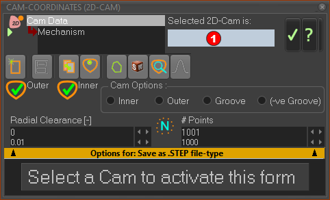 Cam-Data dialog - 2D-Cam ''Not Seleted'' |
||||
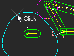 Click to select a 2D-Cam |
To select a 2D-Cam:
The 2D-Cam is now in the Selected 2D-Cam is box - see
|
|||
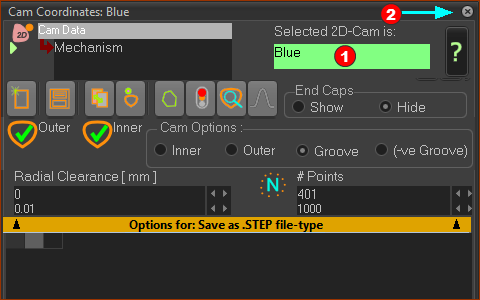 Cam-Data FB : The name of the selected 2D-Cam is "Blue". |
||||
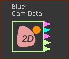 |
Result: In the graphics-area, the caption above the Cam-Data FB has two parts: •Top (Inner in the example): the last calculated Flank of the 2D-Cam that you have selected. •Bottom Line (Blue in the example): the element-name of the Cam-Data FB - see TOP-TIP You can: •Analyze 5 Cam parameters - see Cam-Analysis Parameters •Calculate the Cam's Coordinates - see Cam-Coordinates dialog |
|||
TOP-TIP:
|
||||
STEP 3: Connect wires to a Graph FB
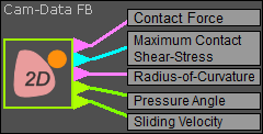 Analysis Parameters from Cam-Data FB |
|||||||
The output-connectors from the Cam-Data FB provide over a machine-cycle: •F : Contact Force : see Note 1 •Ԏ : Maximum Contact Shear-Stress : See Note 2 •ρ : Radius-of-Curvature : see Note 3 •μ : Pressure Angle : see Note 4 •Ue : Sliding Velocity : see Note 5 Drag wires from the output-connectors of the Cam-Data FB to a Graph FB, a Math FB or a Statistics FB Make sure you select the correct Cam-Profile (Inner, Outer, or Pitch-Center Path) in the Y–axis display option of the Graph FB interface. Configure the Power Source before you analyze the Contact-Force.
Note 2: Maximum Contact Shear-Stress Configure the Power Source before you analyze the Maximum Shear-Stress.
About Maximum Contact Shear-Stress
Top-Tip:
|
After you correctly Configure the Power Source, you can find the Contact-Force and Contact Maximum Shear-Stress between the Cam-Profile and the Follower-Roller. There are four methods to Display in the graphics-area: Method 1: Forces toolbar > Display Force-Vectors button. Two equal and opposite Force-Vectors radiate from the Contact-Point between the Cam-Profile and the Follower-Roller. They are: •the force vector that ACTS-ON the Follower-Profile and Follower-Part •the force vector that ACTS-ON the Cam-Profile and Cam-Part You must analyze if the force between the Cam-Profile and the Follower-Profile is active or not active (less than zero Newtons). Method 2: Use: 2D-Cam dialog > Display tab > Cam Display Options > Contact-Force. Plot with a Graph-FB: Method 3: Add a Force-Data FB, select the 2D-Cam as the Force element, plot with a Graph FB. Method 4: Use the Cam-Data FB to plot Contact Force from the top output-connector with a Graph FB. Contact-Force is = 0 N if Contact-Force ≤ 0 N. Note: Method 4 is best if you need to know if the Contact-Force is less than or equal to zero |
