2D-Cam
See also : Cam-Terminology
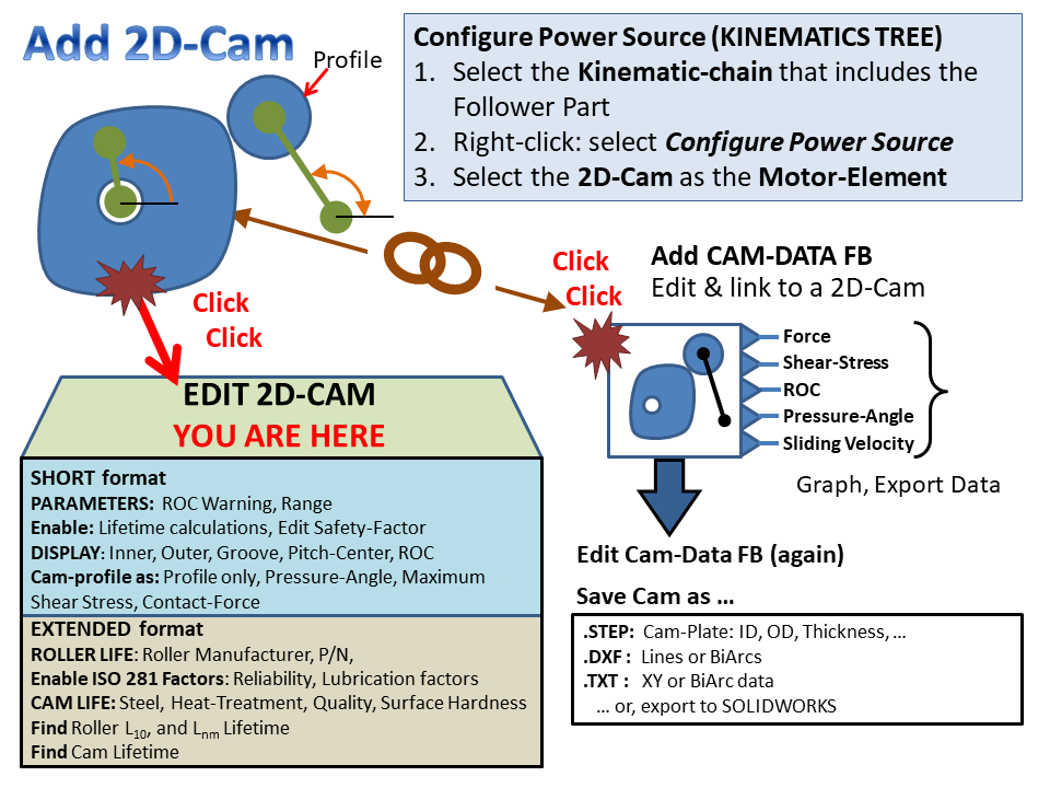
2D-Cam Work-flow
|
||||||||||||||||||||||||
To open the 2D-Cam dialog:
The 2D-Cam dialog is now open. |
2D-Cam dialog
The 2D-Cam dialog has two formats:
SHORT format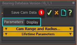 |
EXTENDED format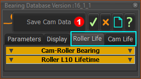 |
The two tabs are: ParametersDisplay |
The two NEW tabs are: Roller LifeCam Life |
Click Save Cam Data at the top of the dialog to save the data to a CSV file-type. The CSV file saves the parameters and the data at each step in the machine cycle. The CSV saves the Roller-Life and the Cam-Life details when you enable Roller and Cam Lifetime.
IMPORTANT: Do not use the X-Y coordinates that you can save with this dialog to manufacture the cam. Use a Cam-Data FB to calculate and save the Cam-Profile as XY-Point, BiArcs, and STEP file-type. Note: If you open the file in Excel > Data tab > Data and Transform data group > From Text/CSV file, use Unicode UTF-8 (65001) as the File Origin. See also: The output connectors of the Cam-Data FB for other analysis of the 2D-Cam. |
 |